Home

Chemicaliën vocaal ingesteld inverter output power calculation meditatie Verplicht over het algemeen

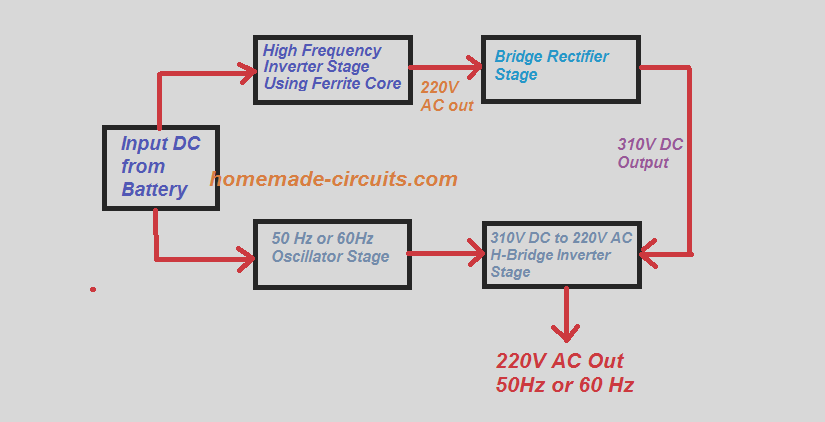
5kva Ferrite Core Inverter Circuit - Full Working Diagram with Calculation  Details - Homemade Circuit Projects
5kva Ferrite Core Inverter Circuit - Full Working Diagram with Calculation Details - Homemade Circuit Projects

What is a frequency inverter?

E-Learning Power Electronics

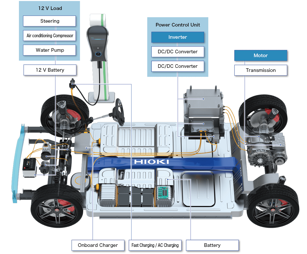
Measuring Dynamic Motor Characteristics | HIOKI E.E. CORPORATION

Simulated output voltage of an inverter when input voltage is 0 V, as a...  | Download Scientific Diagram
Simulated output voltage of an inverter when input voltage is 0 V, as a... | Download Scientific Diagram

Solar Power Inverter - MATLAB & Simulink

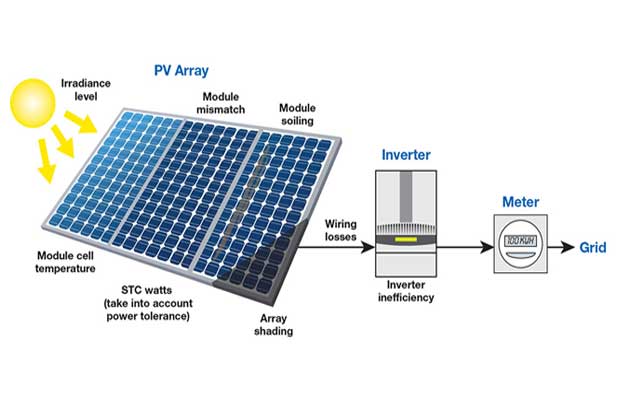
Here is how you can calculate the annual solar energy output of a  photovoltaic system
Here is how you can calculate the annual solar energy output of a photovoltaic system

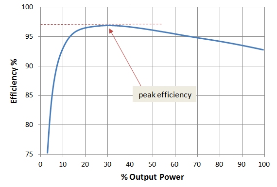
6.5. Efficiency of Inverters | EME 812: Utility Solar Power and  Concentration
6.5. Efficiency of Inverters | EME 812: Utility Solar Power and Concentration

Teardown: The power inverter - from sunlight to power grid - EDN

Loss Calculation in a Three-Phase 3-Level Inverter - MATLAB & Simulink -  MathWorks 中国
Loss Calculation in a Three-Phase 3-Level Inverter - MATLAB & Simulink - MathWorks 中国

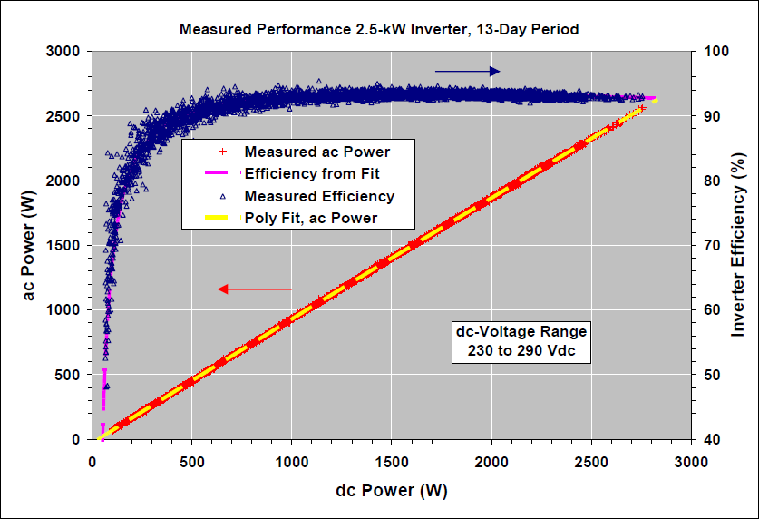
Performance Model for Grid-Connected Photovoltaic Inverters - ESIG

Design of output LCL filter and control of single-phase inverter for  grid-connected system | SpringerLink
Design of output LCL filter and control of single-phase inverter for grid-connected system | SpringerLink
Phase shift, d, between inverter output voltage, V inv , and grid... |  Download Scientific Diagram
Phase shift, d, between inverter output voltage, V inv , and grid... | Download Scientific Diagram

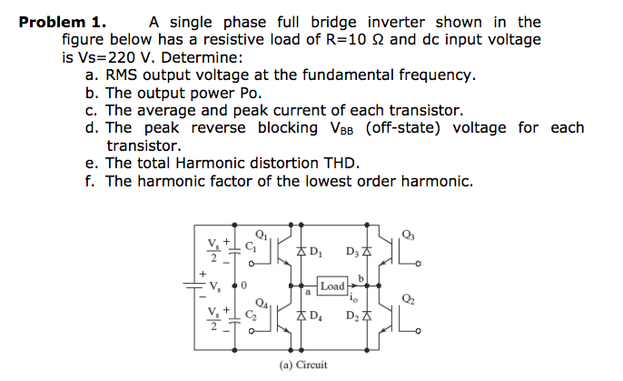
Solved Problem 1. A single phase full bridge inverter shown | Chegg.com

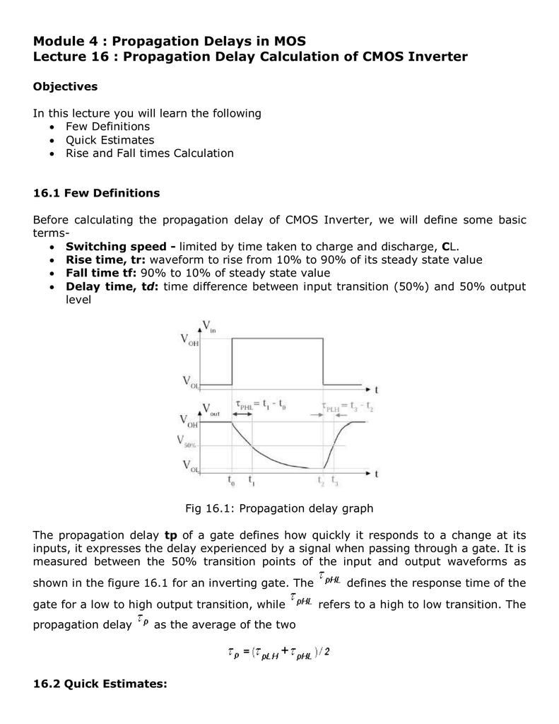
Propagation Delay Calculation of CMOS Inverter

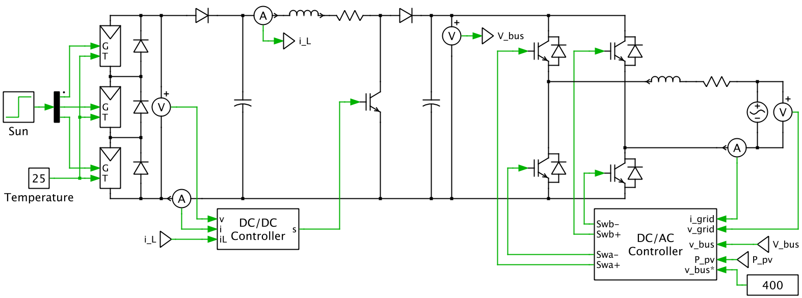
Single-Phase, Grid-Connected PV Inverter with Partial Shading (Equation-Based  PV Cell, P&O and dP/dV MPPT) | Plexim
Single-Phase, Grid-Connected PV Inverter with Partial Shading (Equation-Based PV Cell, P&O and dP/dV MPPT) | Plexim

Measuring Dynamic Motor Characteristics | HIOKI E.E. CORPORATION

Inverter Specifications and Data Sheet | Electrical Academia

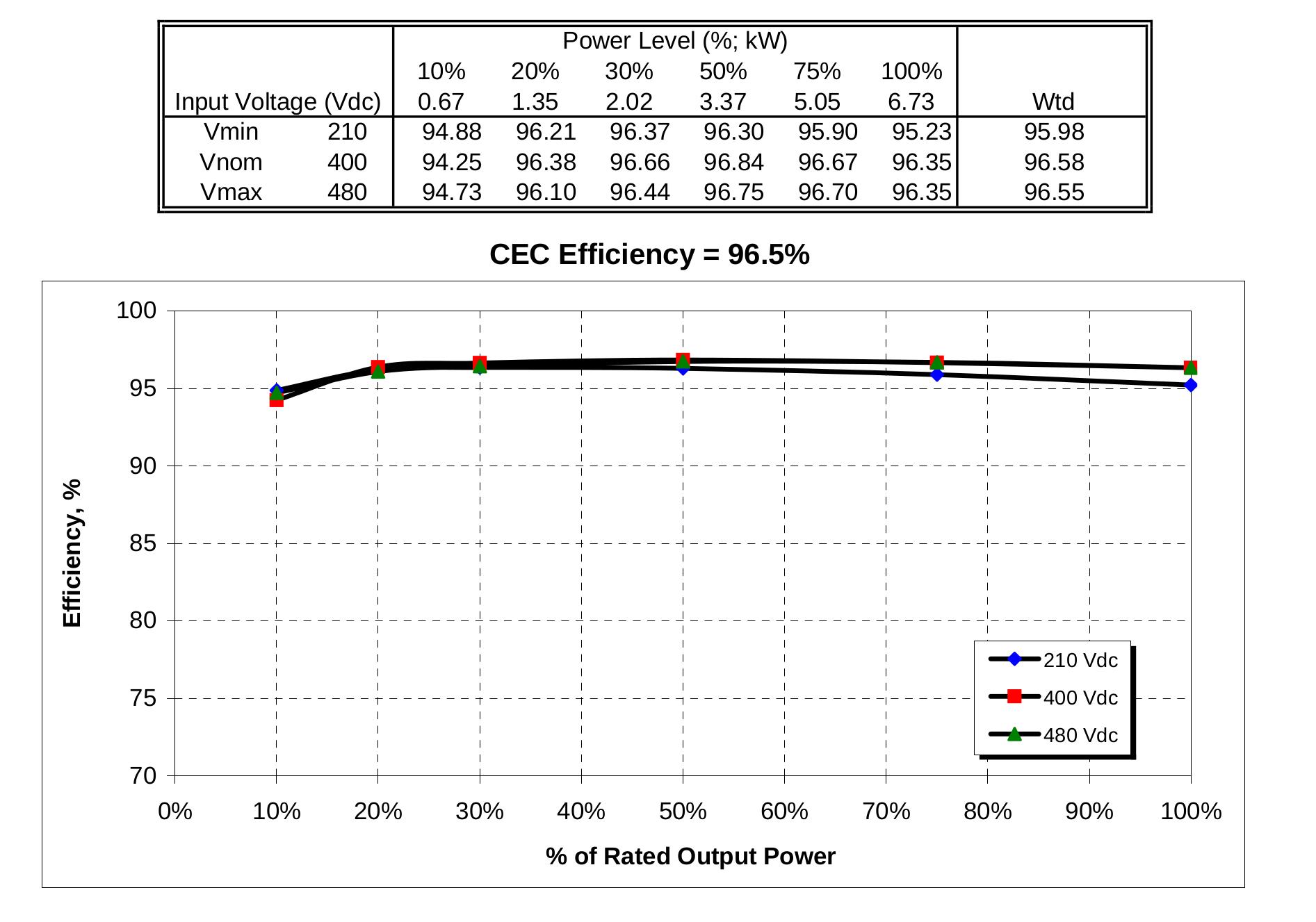
PV Performance Modeling Collaborative | CEC Inverter Test Protocol

Efficiency of Inverter: Calculation & Equation Formula Guide | Linquip

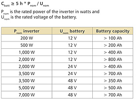
Inverter Selection
Inverter Selection

a). Inverter Output Voltage for RL Load | Download Scientific Diagram

How to calculate output power of a multi-MPPT inverter? - Electrical  Engineering Stack Exchange
How to calculate output power of a multi-MPPT inverter? - Electrical Engineering Stack Exchange

Power losses calculation methodology to evaluate inverter efficiency in  electrical vehicles | Semantic Scholar
Power losses calculation methodology to evaluate inverter efficiency in electrical vehicles | Semantic Scholar

1 AlMustansiriya University Faculty of Engineering Electrical Engineering

How to Calculate Inverter Power Rating and Inverter Battery Backup Time ~  Learning Electrical Engineering
How to Calculate Inverter Power Rating and Inverter Battery Backup Time ~ Learning Electrical Engineering

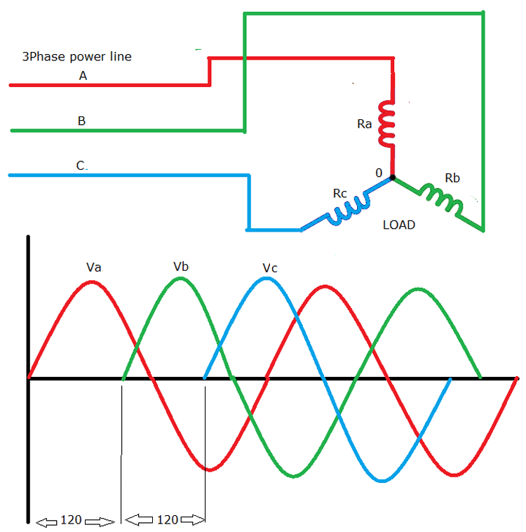
Three Phase Inverter Circuit Diagram - 120 Degree and 180 Degree Conduction  Mode
Three Phase Inverter Circuit Diagram - 120 Degree and 180 Degree Conduction Mode