Home

Behandeling knoop innovatie buck boost converter duty cycle calculation Plons methaan charme

The Low Output Voltage Ripple Zeta DC/DC Converter Topology | Analog Devices

1. INTRODUCTION 2. BASIC BUCK-BOOST CONVERTER OPERATION 3. THREE PHASE  VOLTAGE SOURCE INVERTER MODEL 4. SIMULATION RESULTS AND DISCUSSION 5.  CONCLUSION REFERENCES POWER LOSS ANALYSIS MODEL OF A ...
1. INTRODUCTION 2. BASIC BUCK-BOOST CONVERTER OPERATION 3. THREE PHASE VOLTAGE SOURCE INVERTER MODEL 4. SIMULATION RESULTS AND DISCUSSION 5. CONCLUSION REFERENCES POWER LOSS ANALYSIS MODEL OF A ...

Upper End Limitations of a Duty Cycle | Analog Devices

Introduction to DC-DC Conversion – Cont. - ppt video online download

Effect of duty cycle on (L,C) design of buck-boost converter. | Download  Scientific Diagram
Effect of duty cycle on (L,C) design of buck-boost converter. | Download Scientific Diagram

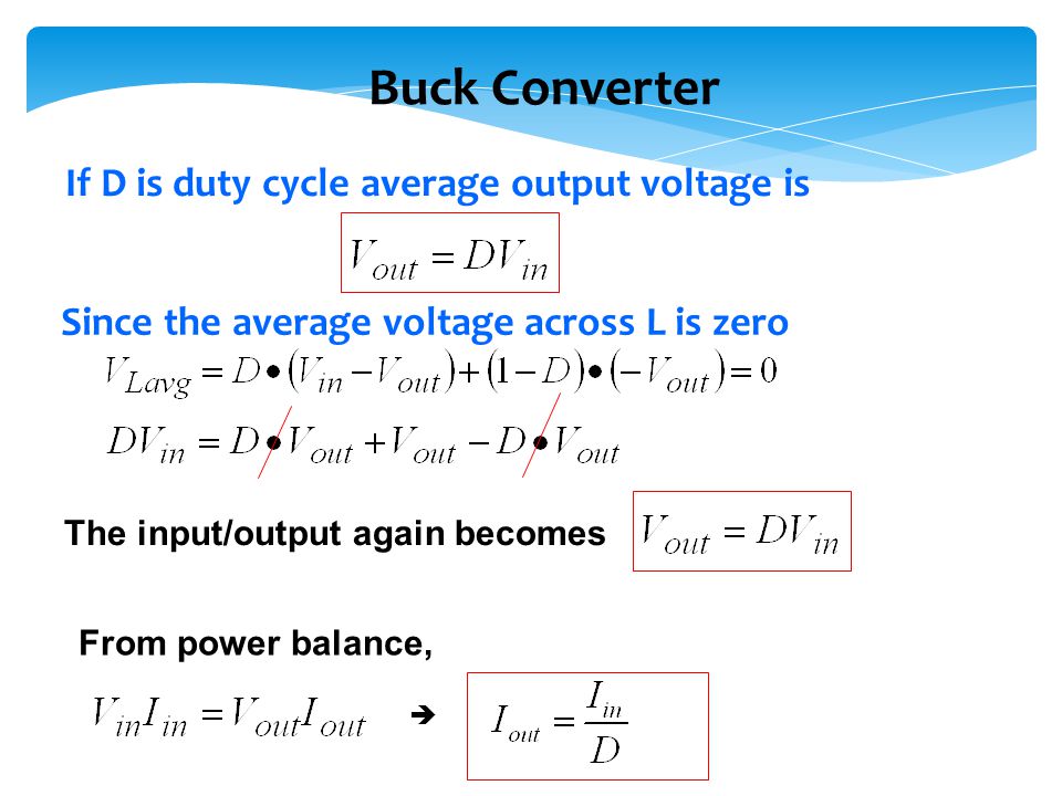
Buck Converter Duty Cycle Derivation | ElectronicsBeliever

Table I from The comparative study of Buck-boost, Cuk, Sepic and Zeta  converters for maximum power point tracking photovoltaic using P&O method |  Semantic Scholar
Table I from The comparative study of Buck-boost, Cuk, Sepic and Zeta converters for maximum power point tracking photovoltaic using P&O method | Semantic Scholar

DC-DC converter DCM analysis - NXP Community

DC to DC buck-boost converter circuit homemade

In a Buck-Boost converter, L=25 μΗ. It is operating in dc steady state  under the following - HomeworkLib
In a Buck-Boost converter, L=25 μΗ. It is operating in dc steady state under the following - HomeworkLib

Buck Converter Design Tutorial - Complete Equation Derivation and Design  Sample
Buck Converter Design Tutorial - Complete Equation Derivation and Design Sample

The DC-DC Boost Converter – Power Supply Design Tutorial Section 5-1 -  Power Electronics News
The DC-DC Boost Converter – Power Supply Design Tutorial Section 5-1 - Power Electronics News

Power Electronics Lecture10 D C to D C

How to Calculate the Duty Cycle of Boost Converter | ElectronicsBeliever

For buck-boost converter, (a) duty ratio, (b) inductor current, (c)... |  Download Scientific Diagram
For buck-boost converter, (a) duty ratio, (b) inductor current, (c)... | Download Scientific Diagram

Solved Question 5 a For the buck-boost converter shown in | Chegg.com

Book excerpt: Switching Power Supply, Design and Optimization, CHAPTER 4,  Part 1 of 2 - EDN
Book excerpt: Switching Power Supply, Design and Optimization, CHAPTER 4, Part 1 of 2 - EDN

Buck-Boost Converter Analysis

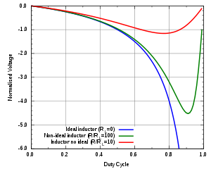
Buck–boost converter - Wikipedia

Buck-Boost Converter: What is it? (Formula and Circuit Diagram) |  Electrical4U
Buck-Boost Converter: What is it? (Formula and Circuit Diagram) | Electrical4U

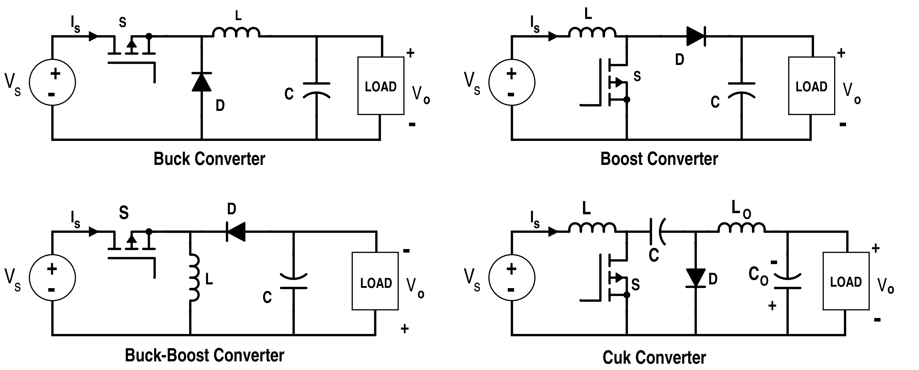
Analysis of Four DC-DC Converters in Equilibrium - Technical Articles

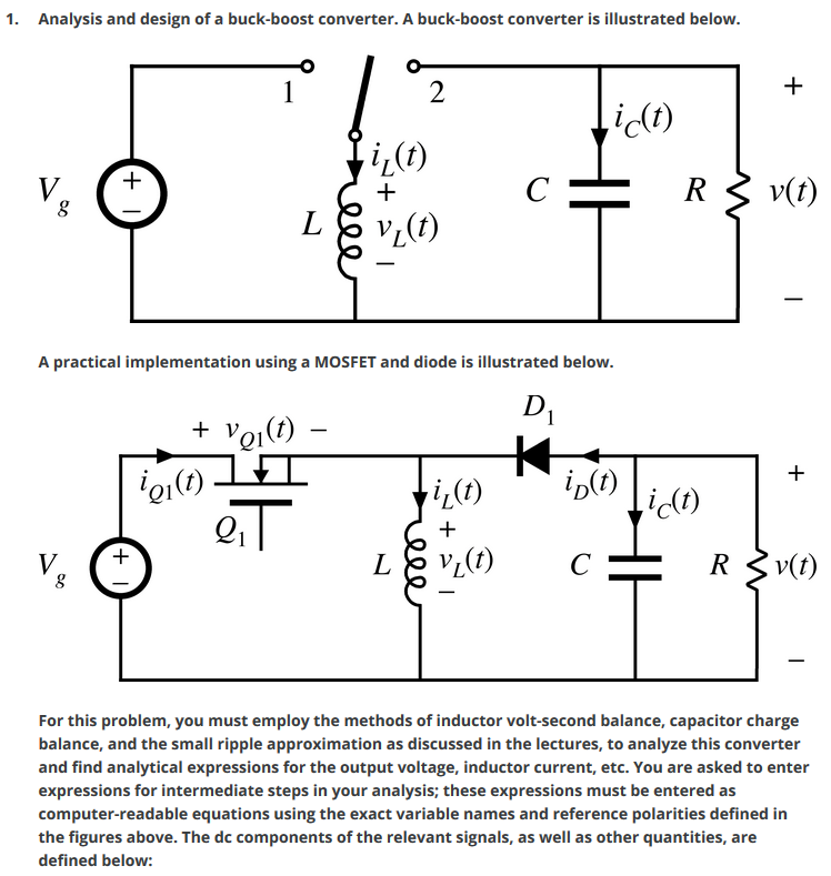
Solved 1. Analysis and design of a buck-boost converter. A | Chegg.com

Buck converter duty cycle | All About Circuits

Buck–boost converter - Wikipedia

The DC-DC Boost Converter – Power Supply Design Tutorial Section 5-1 -  Power Electronics News
The DC-DC Boost Converter – Power Supply Design Tutorial Section 5-1 - Power Electronics News